Proposal:Power routing proposal
| Power routing proposal | |
|---|---|
| Proposal status: | Draft (under way) |
| Proposed by: | Surly |
| Tagging: | power=circuit |
| Applies to: | |
| Definition: | Determine the best tagging model to use to map power circuits all along power grids supported by power=line ways. |
| Statistics: |
|
| Draft started: | 2013-03-11 |
This proposal is designed to set up a good tagging model and best practices to allow routing on power grids mapped on OSM.
It is based upon ![]() Bahnpirat (on osm, edits, contrib, heatmap, chngset com.)'s work and
Bahnpirat (on osm, edits, contrib, heatmap, chngset com.)'s work and ![]() Surly (on osm, edits, contrib, heatmap, chngset com.) point of view published on Power_lines page.
Surly (on osm, edits, contrib, heatmap, chngset com.) point of view published on Power_lines page.
Rationale
As described on many power grid operators' websites, power lines ways don't reflect the real power exchange path. Since OSM uses a relational model to link up path ways, it's possible to define a tagging model to design power circuits as relation between power lines ways on the map.
You may find a little description of how power circuits works on circuits=* page.
Power routing in OSM
Here are the two main point of view which had been expressed on OSM so far. The first one is in favor of type=route + route=power to map circuits since the power exchange is not so different of public transportation networks. The second aim to totally distinguish power routes and transport routes and gives a brand new tagging model.
Tagging similar to Transportation routes
This method of tagging should be deprecated. To save the history the description of this method is moved to the special page.
Tagging power circuits with a relation
Power line routes are not similar to transportation routes. Power lines have exactly two end point and have no "stops" in the middle. The beginning and the end (source and consumer of energy) of the line may exchange sometimes (e.g. in case of emergency switching). A power line may have T-shape connection to another one, but it is not an intermediate stop, it is a beginning of the other line. Also there are no traveling things like buses, passengers or travelers as in "common" routes. A traveling of electrons is rather physical abstraction, and it is not so simple as "small moving balls".
The relation for power circuits must be able, ideally, to tag splitting of phases to individual towers and gathering of them together; T-shaped circuits connections; supporting structures when part of wire does not transmit electricity but only acts as a holding device.
Among other issues, a special relation will help us not to confuse, when we make a map of transportation routes. Because a map of traveling routes and a map of power lines are different kinds of maps. In case of special relation for power lines a software will not have to analyze the values of route=* (is it equal to "power" or not?) but may rely on a type=power only.
So the structure of this relation is very different from structure of a route relation. That is why we should not tag power circuits with type=route + route=power. We should think about a special relation, and I suggest type=power + power=circuit for this purpose.
Tagging: a simple case
Relation
A relation of this type collects power line ways that constitute the same power circuit, with the same electrical characteristics, name and reference mark.
| Key | Value | Mandatory? | Comment |
|---|---|---|---|
| type | power | Mandatory | category of relations |
| power | circuit | Mandatory | power circuit routing |
| ref | * | Recommended | Reference number, name, signature or another naming of the circuit |
| name | * | ||
| short_name | * | ||
| voltage | * | Recommended | Electrical characteristics of the circuit |
| frequency | * | ||
| cables | * | ||
| wires | * |
Members
example (simple case)
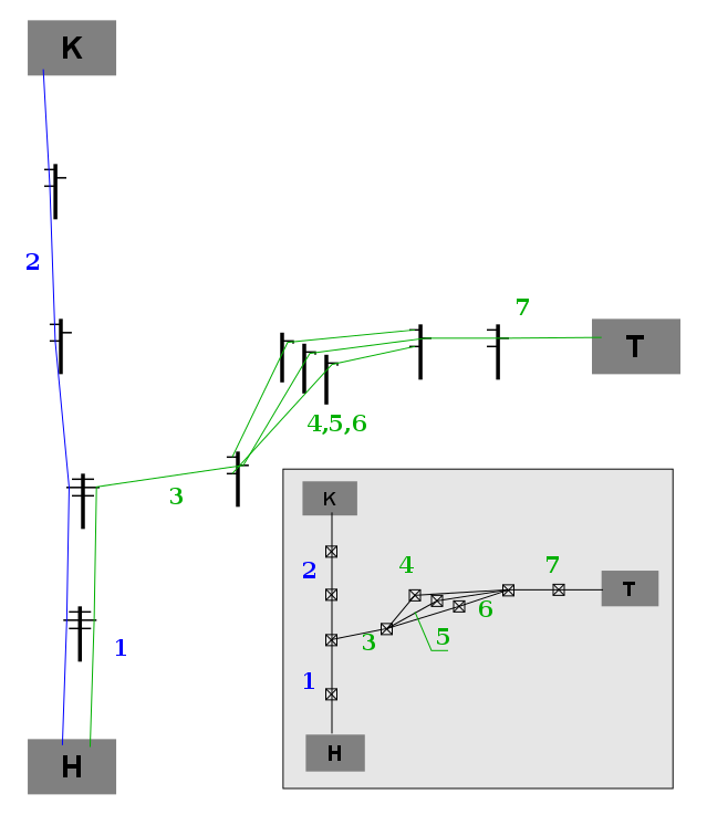
The folowing drawing illustrates a connection of the substation "H" with two other substations: "K" and "T".
At the substation "H" both of the circuits run on the same towers (line segment 1), then split (the segments 2 and 3). Then the phases of the circuit "H—T" split (4,5,6) and then gather together again (line 7).
Tagging relations
| Relation | Relation's tags | Relation's members, in the folowing order |
|---|---|---|
| type=power power=circuit cables=3 ref=H-K |
||
| type=power power=circuit cables=3 ref=H-T |
Tagging ways and polygons:
| Way | ||||||||||
|---|---|---|---|---|---|---|---|---|---|---|
| Tags | power=substation ref=H |
power=substation ref=K |
power=substation ref=T |
cables=6 circuits=2 |
cables=3 circuits=1 |
cables=3 circuits=1 |
cables=1 circuits=1 phase=L1 |
cables=1 circuits=1 phase=L2 |
cables=1 circuits=1 phase=L3 |
cables=3 circuits=1 |
Advanced cases: branching
This part of the proposal describes tagging for power line branching. The purpose of this tagging model is to describe which branch circuit, where and to which trunk circuit connects. A relation is proposed to describe such branching.
Relation
| Relation's tag | Member | Description |
|---|---|---|
| type=power | Required | The relation describes a power network feature |
| power=branch | Required | The relation describes a circuit branching |
| ref=* | Optional | If the branch is marked with ref number |
| *=* | Optional | Any tag that describes the connection itself |
Members
| Member's role | Count | Member | Description |
|---|---|---|---|
| One (or zero) | Trunk circuit's relation | Recommended. May be omitted if the trunk circuit is not mapped with a | |
| One (or zero) | Branch circuit's relation | Recommended. May be omitted if the branch circuit is not mapped with a | |
| One (or zero) | The point (tower) where circuits are connected | Recommended. May be omitted if the connection point is unknown or unmapped. | |
| Zero or more | Trunk circuit's line (the way closest to the connection) | Optional. Recommended if the trunk circuit is not mapped with a | |
| Zero or one | Branch circuit's line (the way closest to the connection) | Optional. Recommended if the branch circuit is not mapped with a |
example (branching case)
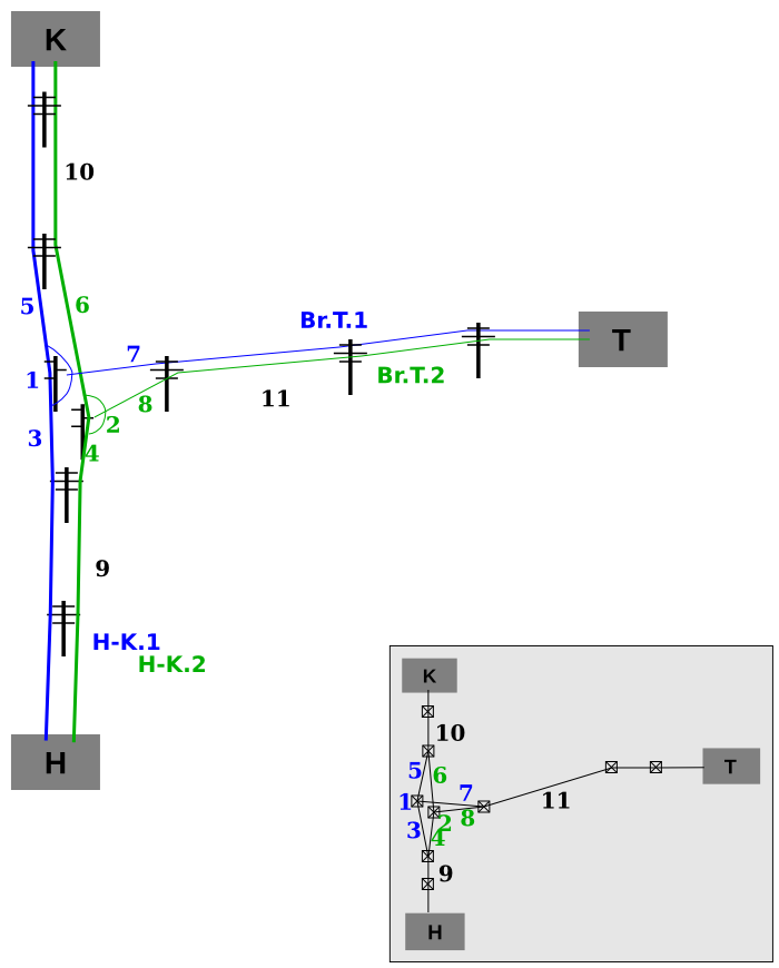
The substations "H" and "K" are connected with two power circuits marked as "H-K.1" and "H-K.2". At the line segments 9 and 10 both of the circuits run on the same towers. Towers 1 and 2 are branch pylons where a brach circuits are connected; so trunk circuits at the line segments 3, 4, 5, and 6 run separately. The substation "T" connects to the trunk line with branch circuits marked as "Br.T.1" and "Br.T.2". The circuit "Br.T.1" (segment 7) is connected to the trunk circuit "H-K.1" at the pylon 1, and the circuit "Br.T.2" (segment 8) is connected to the trunk circuit "H-K.2" at the pylon 2. Then both of the branch circuits run on the same towers to the substation "T".
![]() The relation for "H-K.1" circuit:
The relation for "H-K.1" circuit:
| Tag or role | Key | Value or member |
|---|---|---|
| tag | type | power |
| tag | power | circuit |
| tag | ref | H-K.1 |
| tag | cables | 3 |
| role | line | |
| role | endpoint |
![]() The relation for "H-K.2" circuit:
The relation for "H-K.2" circuit:
| Tag or role | Key | Value or member |
|---|---|---|
| tag | type | power |
| tag | power | circuit |
| tag | ref | H-K.2 |
| tag | cables | 3 |
| role | line | |
| role | endpoint |
![]() The relation for "Br.T.1" circuit:
The relation for "Br.T.1" circuit:
| Tag or role | Key | Value or member |
|---|---|---|
| tag | type | power |
| tag | power | circuit |
| tag | ref | Br.T.1 |
| tag | cables | 3 |
| role | line | |
| role | endpoint |
![]() The relation for "Br.T.2" circuit:
The relation for "Br.T.2" circuit:
| Tag or role | Key | Value or member |
|---|---|---|
| tag | type | power |
| tag | power | circuit |
| tag | ref | Br.T.2 |
| tag | cables | 3 |
| role | line | |
| role | endpoint |
![]() The relation for the first connection:
The relation for the first connection:
![]() The relation for the second connection:
The relation for the second connection:
Comments
Comments are welcome on the talk page :)
Feel free to comment each of schemes described above.
Voting
The voting has not started yet.

