Tag:power=transformer
| Description |
|---|
| A device for stepping up or down electric voltage. Large power transformers are typically located inside substations |
| Group: power |
| Used on these elements |
| Useful combination |
| Status: approved |
| Tools for this tag |
|
A power transformer[1] is a static device which converts a given power voltage to another power voltage. A transformer may be located within a power=substation.
In more technical terms, a power transformer is composed of two or more windings which, by electromagnetic induction, transforms a system of alternating voltage and current into another system of voltage and current for the purpose of transmitting electrical power. The delivery is done at the same frequency than the input.
How to map
A transformer is tagged as a ![]() . Transformers are usually located within substations and should be tagged as a node within an area tagged as power=substation.
. Transformers are usually located within substations and should be tagged as a node within an area tagged as power=substation.
It is not recommended to mix them with buildings. In case of indoor transformers, place a node inside the building area and add location=indoor on it.
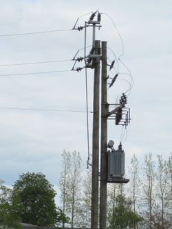
For pole mounted transformers it is suggested to tag the pole as power=pole and add the tag transformer=distribution (or transformer=yes).
Advanced mapping
Many details about the transformer can be added using a more complete tagging scheme. It is particularly intended for mappers having some knowledge about power systems.
Finding transformer data
First of all, don't go inside power substations if you're not invited to do so please, it's dangerous and probably illegal. Public information or aerial imagery will help to see outdoor transforming facilities safely.
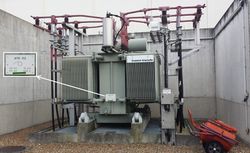
High detailed information may be found on transformers themselves. A complete datasheet as exposed beside gives many figures on the machine capabilities and structure.
We basically need voltages, windings structure but manufacturer=* and start_date=* may also be completed.
Nevertheless, you may not be able to take a picture of those plates and as a reminder: don't go inside restricted perimeters to get the one you couldn't unless invited.
Tagging
| Key | Value | Comment | Recommendation |
|---|---|---|---|
| power | transformer | Defines this node as a transformer. | Mandatory |
| transformer | <purpose>, defaults to main | The purpose of transformer (see transformer for values). The vast majority of transformers do not require tagging with a special purpose. | Recommended |
| location | <location> | The location of the transformer. See below for possible values. If the location of the transformer is the same as that of its substation this tag is optional. | Recommended |
| frequency | <numeric> as Hz | The frequency of the transformer in hertz (Hz). Recommended if the frequency differs from that of the general power grid, for example 16.7 Hz for the German railway traction grid. | Recommended |
| <numeric> as V | The operating voltage of a given interface of the transformer. Don't use voltage globally since it's not relevant for a transformer. See transformer interfaces chapter below for more information. | Recommended | |
| 1, 3, .. | Number of phases of the whole transformer or more precisely on a given interface. Recommended tag for single-phase transformers/interface. Default is 3. | Optional | |
|
<numeric> <unit> Units: VA, kVA, MVA, or GVA |
The apparent power rating of the whole transformer, or of a specific interface. The units of measure are near-universally multiples of volt–amperes, but nonetheless must be explicitly provided: following the numeric value and separated by space. Valid examples: "2.5 MVA", "1000000 VA". Invalid examples: |
Optional | |
| 1, 2, 3, ... | Number of windings in the whole transformer or more precisely on a given interface. See Transformers interfaces chapter below for more information | Optional |
Location values
| Key | Value | Comment |
|---|---|---|
| location | outdoor | A transformer located outside in open air. Use this value even if the transformer is (partly) surrounded by protective walls. This is the default value. |
| indoor | A transformer located inside a building. | |
| underground | A transformer located underground. | |
| rooftop | A transformer located on top of a building that is used for something else. |
location=kiosk was used to map small boxes, often manufactured and too small to be considered as actual building, hosting a transformer. man_made=street_cabinet + utility=power are more suitable to do so and get back location=* to give the cabinet's actual position (underground, indoor...)
Be careful to not confuse with substations, mapped with power=substation + substation=minor_distribution (see examples) which have more devices than only a transformer inside.
Transformers interfaces
Transformers are designed to adapt voltage between their windings connected to interfaces. Interfaces are used to be called primary, secondary and so on. Several windings can compose a single interface (we find sometimes 2 or more windings on secondary interfaces of distribution source transformers). Transformers are always able to forward power in every direction they connect to.
Complex situations may occur and need extended keys to be accurately described in OSM. phases=*, rating=*, windings=* may be suffixed with :primary, :secondary, :tertiary, ... to give as specific values as it needs for a specific interface. If no suffix is used, the values will be considered as common to all interfaces of the transformer. All windings related to an interface (primary, secondary, ...) always operate at the same voltage. Electrical parts with different voltages cannot belong to the same the interface.
Voltage tagging
The convention OSM reviewed makes primary on the original producer side, like power generator or distant power plant whereas other sides including secondary sees consumers. Tertiary, quaternary and further sides are intended for lower voltages auxiliary services inside power plants or substations. Most producers usually step up their voltages for transmission (generator) toward consumers which makes by convention primary > secondary anywhere else in the infrastructure even if energy can actually flow in all directions on many intermediate nodes.
The most important for OSM is the consistency between transformer=* and voltages, particularly for facilities that both produce and consume power at different times. No choice is wrong when values are consistent.
Each interface is defined with its own voltage and transformers won't have a global voltage value. Use of voltage=* without suffix is discouraged on transformers. You are invited to use voltage:primary=*, voltage:secondary=* or voltage:tertiary=* instead according to the interface's name.
| Key | Value | Description |
|---|---|---|
| voltage:primary=* | Primary interface's voltage | The operating voltage of a given transformer's primary interface. |
| voltage:secondary=* | Secondary interface's voltage | The operating voltage of a given transformer's secondary interface. |
| voltage:tertiary=* | Tertiary interface's voltage | The operating voltage of a given transformer's tertiary interface. |
More voltages may be added following this way, depending on transformer's architecture you intend to describe.
voltage-high=* and voltage-low=* are in use in many places. Some mappers may be more confident by using high and low voltages. However these high and low collide with high and low voltages (like high voltage for transmission and low voltage for domestic usage) and transmission transformers deal with two different high voltages for instance. Not to mention there are often more than two voltages in transformers used in transmission networks.
Such information may help match both ways as following:
- voltage-high=* = voltage:primary=* and voltage-low=* = voltage:secondary=* in case of down transforming, anywhere outside a power generating facility. The power normally flows from higher voltage grid to lower voltage grid towards consumers.
- voltage-high=* = voltage:secondary=* and voltage-low=* = voltage:primary=* in up transforming places like power plants, for generator only. Generators produce pretty low voltage power whereas transmission power grids operate at very high voltage. According to convention, the power generator side is definitely the primary interface and here at lower voltage than the secondary connected to power grid.
Windings configuration
Since a transformer is composed of several windings, with many different possible configurations, see windings=* for more information.
We can describe the windings configuration with windings:configuration=* and auto design with windings:auto=*.
Transformer sets
In some situations and countries, polyphase transformers may not be contained in a single unit. It's not unusual to find several single phase transformers units assumed as an equivalent to a single polyphase transformer. It is recommended to use transformer:devices=*, which defaults to 1, to indicate how many different transformers you see, sharing the same figures and functions.
Such a key will factorise as many features as possible on a same node. Thus, all keys indicating transformer capacities will have to be valued for a single device.
More examples are available below, here's the principle : 2 similar three-phase 50Hz transformers may be factorised on the same node in this manner : devices=2 + phases=3 + frequency=50.
Please note that, according to IEC 151-12-11, such disposal of transformers can't be properly called a bank since the transformers aren't connected together but each to a different phase (or even different power circuit). A set would be more appropriate.
An actual bank can't be factorised on the same node (even if at the top of a pole) and for sake of accuracy, you'll have to use as many nodes as devices in the bank. If not, we loose information about the bank structure and how transformers are working together.
Examples
Here you see a few examples to show the main possibilities of transformer. See each transformer=* values examples for more occurrences.
| Photo | Location | Tagging | Note |
|---|---|---|---|
 |
Germany |
|
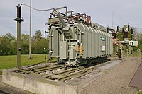
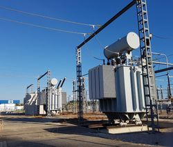
Large outdoor power transformer in a transmission power substation. |
 |
Denmark |
|
Typical pole mounted 10 kV transformer. |
 |
United States |
power=pole
|
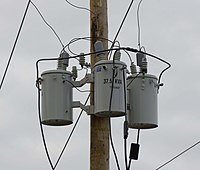
Multiple single phase transformers used on a 3-phase network. |
 |
France |
power=transformer
|
Such transformer are used in France to feed legacy 15kV distribution zones from current 20kV infrastructures.
Visible sign show us operational voltages of both sides and that the transformer works as an auto-transformer. |
 |
France |
power=transformer
|
High speed rail lines are fed from transmission power grid with such biphase transformers.
These are main transformers in traction substations. More information about French 50 kV traction system on this chart |
 |
France |
power=transformer
|
Two auxiliary transformers, tagging is valid for the bigger white one. The smaller grey one convert from 20 kV to 400 V to feed the substation's premises only. |
See also
- Proposed features/Substation refinement: The approved substation proposal including the transformer stuff.
- Proposed features/Transformer extension proposal: The approved extension proposal for power transformers defining most of advanced tagging of this page
- Proposed features/Transformers classification refinement: The approved classification proposal for power transformers introducing transformer=main and windings:auto=*
References
- ↑ See also IEC-ref 421-01-01 at electropedia.org for a definition: http://www.electropedia.org/iev/iev.nsf/display?openform&ievref=421-01-01
