Tag:power=switch
| Description |
|---|
| A device which allows electrical network operators to power up & down lines and transformers in substations or along the power grid. |
| Group: power |
| Used on these elements |
| Useful combination |
| Status: approved |
| Tools for this tag |
|
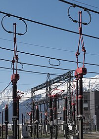
A switching device is intended to break the current in a given power line or equipment. Many sorts actually exist in power grids, at different scales to protect or control how electricity flows through the network both for maintenance or security purposes.
To know where and how they operate in the network can allow data consumers to improve a lot their own comprehension of such systems.
How to map
Please don't go inside power substations if you're not invited to do so, it's dangerous and probably illegal.
Aerial imagery will help to see outdoor switching facilities safely.
On every switching device found looking like examples at the bottom of this page, add a ![]() and put some tags described below. Use location=* to give information about its position and switch=* to let us know about its function.
and put some tags described below. Use location=* to give information about its position and switch=* to let us know about its function.
Inside a substation, you may commonly find switch=circuit_breaker and switch=disconnector which are two kind of power switches with different functions.
Outside a substation, switches are often placed on power lines (both line and minor_line and bot overhead and underground), they can be mounted on a pole or tower. To tag such situations, use switch=* on power=pole, power=tower, power=portal or power=insulator nodes. Switches used on high-voltage power lines power=line (50 kV above) are usually used on tap connections, but on medium-voltage lines (50 kV below), they are used to separate overlapping distribution circuits (in the case of radial connections) and give an area an emergency connection from another substation when the circuit where it belongs is being repaired.
Detailed mapping of power switches
You may find mechanically linked switches as to prevent them to be operated independently (mainly on poly-phase systems). They often have the same figures and functions. You are free to map every single switch with nodes (using cables=1 on each) or placing a single node in the middle of them and use cables=* to give the exact amount of devices.
Elsewhere you may find several switch electrically linked to operate on the same phase or pole. It is strongly recommended to map every single device with a dedicated node since all device won't necessarily have the same figures and functions. If you are sure that electrically cascaded switches have the same figures and functions, then you can use only one ![]() to map them.
to map them.
Tagging
| Key | Value | Comment | Recommendation |
|---|---|---|---|
| power | switch | The switch is normally mapped as a |
Mandatory |
| switch | <switch type> | The functional type or role of the switch. Values are mainly inspired by definitions in this proposal's Rationale. | Recommended |
| location | <location> | The physical location of the switch, such as indoor. See below for possible values. | Recommended |
| voltage | <voltage> | The voltage at which the power switch operates. The switch is mechanically designed to cut two parts of a circuit apart and the voltage is linked to the distance of these two parts when the switch is open. This key is optional since the ways leading to switch are also described with equivalent information. | Optional |
| cables | <number of cables> | A power switch (or group of power switches) can cut several phases, or poles for direct current. If so, just gives the number with this key. Defaults to 1. Please note phases=* is too specific and refers to alternative systems only. A switch can be seen on direct current systems too. Furthermore it can cuts not only phases/lives conductors but neutral too. | Optional |
| gas_insulated | yes | Use this tag for gas insulated switches using pressurized SF6 or SF6/nitrogen gas as insulation medium. Gas insulation allows to reduce distances needed to cut circuits. | Optional |
| operator | <operator> | Name of the company that operates the switch. | Optional |
| ref | <reference> | Abbreviation / number of the switch. | Optional |
Switch values
Location
| Key | Value | Comment |
|---|---|---|
| location | outdoor | A switch located in the open air outside, taking mainly advantage of it to cur power currents. |
| indoor | A switch located indoor. Higher the voltage to cut is high, bigger are the dimensions. Some of them can use special insulating gas. | |
| underground | A switch located underground | |
| platform | A switch placed on a platform | |
| rooftop | A switch located on a rooftop |
And you can obviously add as much precise values as you may need to this incomplete list.
Examples
Examples are focused on substations and distribution networks, where switches can easily be seen. As a common device, you can find many similar shaped devices in many similar places around the world. This example list can be improved as much as needed to allow every mapper to have a better understanding of what all of this is about.
Substation and transmission switches
Sun, mountains and French Alps substations, here you get some big switches. Several pictures are taken from the outside of power facilities. It is possible to safely collect information from the outside without going inside as shown below.
Coupling and power bays
| Photo | Aerial view | Tagging | Note |
|---|---|---|---|
|
Have a look: |
Both coupling and bay circuit breakers have the same tagging. Even if two chambers can be seen on aerial picture, please use only one
|
400 kV busbar coupling dual circuit-breaker. Such devices actually use SF6 as insulation gas. | |
| 400 kV dual circuit-breaker protecting a power bay (where power lines connect to substations). Such devices actually use SF6 as insulation gas. | |||
| -- |
|
A dual switches association in distribution substation. The circuit-breaker is on the transmission side and assume the power grid protection. It has to be operated prior to the disconnector since the power line is surely loaded. The disconnector switches are operated by the distribution operator in maintenance operations when the substation needs to be forced offline. |
Busbar switches
| Photo | Aerial view | Tagging | Note |
|---|---|---|---|
| -- |
Depending on aerial imagery quality, use 1 (cables=3) or 3 nodes (cables=1 on each) with following tags:
|
225 kV busbar switches connecting a power line (coming from the right) to substation busbars (on top).
Mechanically, all 3 switches are linked and can't be operated independently. Mapping with a single node and cables=3 is recommended | |
| -- | As distances aren't so big below 100 kV, only one
|
63 kV busbar switches connecting a power line (going from left to right) to substation busbars (on top).
Mechanically, all 3 switches are linked and can't be operated independently. Mapping with a single node and cables=3 is recommended | |
|
power=switch
|
225 kV disconnector switches connecting both the same power line (going from left to right) to two different substation busbars (on top). Mapping each of them with |
Miscellaneous switches
| Photo | Aerial view | Tagging | Note |
|---|---|---|---|
| |
power=switch
|
225 kV disconnector switch allowing operator to disconnect busbar from coupling chain. | |
|
power=switch
|
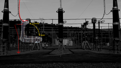
Earthing switch allow to bind a power circuit (normally well insulated from earth) to earth, for maintenance or safety purposes. It can be also found in houses too, at a far smaller scale since the depicted one is for 400 kV circuits.
The horizontal mobile part goes vertical to connect the power line on the top to the earthed lattice on the bottom. |
Distribution switches
Distribution switches can be seen in the country where distribution networks goes aerial. They are often on top of poles.
| Photo | Tagging | Note |
|---|---|---|
 |
power=pole
|
Such switches can be seen on country poles at a distribution level. These have to be operated locally by a technician. |
 |
power=pole
|
Such switches can be seen on country poles at a distribution level. The antenna allows operator to remotely open and close the switch to control the power flow. |
See also
- Proposed features/Substation refinement, introducing this value of power=* key.
- Proposed features/Power switching extension, approved proposal.
- A map of flosm.de where switches are rendered.


