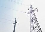
Tag:power=tower
| Description |
|---|
| A tower or pylon carrying high voltage electricity cables. Often constructed from steel latticework but tubular or solid pylons are also used. |
| Rendering in OSM Carto |
| Group: power |
| Used on these elements |
| Useful combination |
|
| Status: de facto |
| Tools for this tag |
|
A power tower, or pylon (![]() Transmission tower) is a large structure used to carry high-voltage electrical transmission lines (power=line). They are traditionally constructed from steel latticework, but different designs such as tubular or solid towers are also sometimes seen.
Transmission tower) is a large structure used to carry high-voltage electrical transmission lines (power=line). They are traditionally constructed from steel latticework, but different designs such as tubular or solid towers are also sometimes seen.
Power lines and their towers are highly visible landmarks and are rendered by general maps such as OSM Carto. Some mappers also add tags describing the appearance, construction, and features of the towers.
- For wooden poles carrying smaller electricity lines, use power=pole
- For poles carrying communications, data, or other cables, use man_made=utility_pole
How to map
Add a node at the centre of the tower and add the power=tower tag. You can add a ref=* as well if the tower has a number. The power=line or lines which are supported by the tower should share the same node.
| Key | Value | Description | Presence |
|---|---|---|---|
| power | tower | A power tower/pylon | Mandatory |
| operator operator:wikidata |
Operating company | The company responsible for operating the pole | Recommended |
| ref | Reference | The reference of the tower as seen on ground. | Recommended |
| location:transition | yes | Used when the tower connects a power line to an underground cable (a "transition tower") | Optional |
| material | steel, wood, concrete, aluminium, composite |
The material of which the tower is mainly composed. | Recommended |
| structure | lattice, tubular, solid |
This tag describes the construction type of a tower. For steel towers (or if no material tag is specified) the default value is lattice. For wooden or concrete towers the default is solid. | Recommended |
| design | (see below) | The style of design of the tower. | Optional |
| design:ref | The specific design that the tower was constructed to. | Optional | |
| height | Height in metres | The height in meter of the tower if known. | Optional |
| colour | Colour as name or RGB triplet | The colour(s) of a painted tower; e.g., colour=red/white for tower painted red and white to make it better visible to pilots. | Optional |
| line_attachment | anchor, suspension, pin |
The way lines are bound to this support. | Optional |
| line_management | Topology | Any particular topology pattern occurring around the support for supported lines. | Optional |
| line_arrangement | Arrangement | Particular arrangements of line bundles supported by the tower | Optional |
| manufacturer | Manufacturing company | The name of the company that built the tower. | Optional |
Tower design
The design=* tag describes the design of the tower. The main parameters are the number and positions of cross-arms. Cross-arms which only serve as support for earth wires should not be considered. See examples with suggested values below.
| Picture | Key | Value | Description |
|---|---|---|---|
|
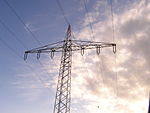
design | one-level | A tower having cross-arms at a single level only supporting a 110 kV line. |
|
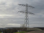
design | two-level | A tower having cross-arms at two levels supporting a 150 kV line. |
|
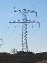
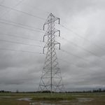
design | donau | A common sub-type of the two-level tower supporting 400kV line in Denmark. It is characterized by having one conductor on each side at the upper level and two conductors at each side on the lower level. The "Donaumast" is widely used in central Europe. |
|
design | three-level | A tower having cross-arms at three levels. |

|
design | barrel | A common variation of the three-level tower. It is characterized by the middle level cross-arms being longer than the upper and lower cross-arms giving the conductor arrangement a barrel-like shape. |

|
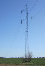
design | asymmetric | A two- or three-level tower carrying only one circuit and having the conductors arranged in an asymmetrical layout. |
|
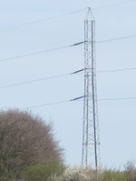
design | triangle | It has cross-arms at three levels providing a triangular arrangement of the conductors. |
|
design | flag | All conductors are located at one side. The tower typically has no or only rudimentary crossarms. This tower type is usually used as an angle tower. |

|
design | donau;one-level | A three-level combination tower effectively being a Donau tower having an additional lower level, often used for circuits of a lower voltage than those at the upper levels. This tag better describes the design than just using "three-level". Similar tag values may be used for other designs having an additional lower level. |

|
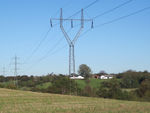
design | four-level, six-level, nine-level, ... |
A tower having cross-arms at four or more levels. These tall towers may carry four or more circuits. |
|
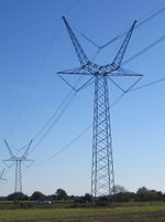
design | delta | A y-shaped tower having a horizontal cross-beam between the two top structures. All 150 kV conductors are attached to the cross-beam. It is mostly used for a single circuit. |

|
design | delta_two-level delta_three-level |
Delta tower having two or three cross-beams. Suitable for three circuits. |
|
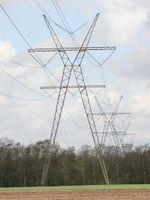
design | y-frame | Similar to delta tower but there is no horizontal cross-beam between the two top structures. The middle conductor is supported directly by the top structures. |
|
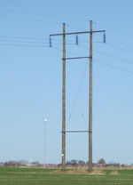
design | x-frame | A variation of the y-frame tower having two legs. It is suitable for carrying a second lower voltage circuit on a crossbeam below the joint. |
|
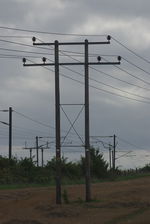
design | h-frame |
A tower type having two (or more) separate pylons or poles connected by a beam to which the 60 kV conductors are attached. The cross-beam extends beyond the vertical structures such that not all conductors are located between the vertical structures. The h-frame tower is mostly used for a single circuit. Also known as pi-poles due to their resemblance to the Greek letter pi (π). |
|
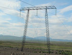
design | h-frame_two-level h-frame_three-level |
Designs like the h-frame tower, but having cross-beams at two or three levels. |
|
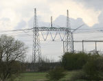
design | guyed_h-frame | A guyed version of the h-frame tower supported by guy wires, common in; e.g. Scandinavia. Compared to the self-supporting h-frame tower this design normally has non-vertical legs. This detail is useful for distinguishing self-supporting towers from guyed towers in aerial imagery etc, since the guy wires are usually too thin to be directly visible in such imagery. |
|
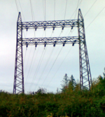
design | portal | A tower type having two (or more) vertical structures connected by a horizontal cross-beam. All conductors are supported between the vertical structures (unlike the h-frame tower). This design is mostly used as termination tower at substations. It can also be used if a line intersects with other power lines. |
|
design | portal_two-level, portal_three-level |
Two and three level versions of the portal tower. |

|
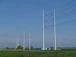
design | guyed_v-frame | A guyed tower type that is mainly used for 735 kV ultra-high voltage lines; e.g., in North America. |
|
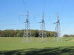
design | bipole | A pair of closely spaced but non-touching pylons. The conductors are typically mounted between the pylons. There are no cross-arms. Known as 'Wintrack' in the Netherlands. The bipole should be mapped as a single tower. |
|
design | monopolar | A tower having no cross-arms, with insulators mounted on the tower itself. Mostly used as an anchor tower at very high voltage.This tower type is typically used in groups of three, with each carrying one phase. There are two recommended options for mapping such a group. Either map all three towers and connect the power line to the middle tower. Or map only one tower and add the attribute triple_tower=yes to the tower. |
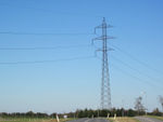
| design:name | * | When the tower design has been given a specific name by its designer it can be indicated by this tag, such as Wintrack (The Netherlands), Eagle (Denmark). | |
|
design:incomplete | yes | An incomplete tower carries fewer conductors than the design is capable of. Sometimes the unused cross-arms are omitted (but can be retrofitted if an extra circuit is to be mounted). |
Some designs uses guying. For mapping these objects, see Tag:man made=guy.
Tower roles
This section deals with the functional role of power towers, such as anchorage or branching lines. Please note that the tower:type=* combination with power=tower has been discouraged and line_attachment=* or line_management=* are now recommended.
| Picture | Key | Value | Description |
|---|---|---|---|
|
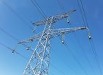
line_attachment | suspension | A tower which supports the conductors vertically using suspension insulators. This is the default type and need not be tagged. However it may be useful to tag a suspension tower if it is used as an angle tower (an anchor tower would normally be expected here). |

|
line_attachment | anchor | A tower where conductor sections terminate at strain insulators. It is normally built stronger than suspension towers. Mostly used as angle tower when the line changes direction. |
|
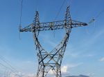
line_management | termination | A tower with strain insulators used at the end of a line with no connection with any other line. Designed to resist the full one-sided tension of the conductors. |
| line_management | branch | A line branch starts at this tower and connects to a continuous main line. If the branch line is a cable then add location:transition=yes. | |

|
line_management | split | Two or more independent circuits coming from the same origin diverge and continue to different direction at this support. |
| line_management | cross | Two or more distinct power lines coming from different directions punctually share a support without any connection | |

|
line_management | transpose | A tower at which the conductors exchange positions in order to balance the capacitance and impedance of a power circuit. |

|
design=* and/or height=* | Actual tower design or height | A special tower used at river crossings etc where a very long span or a large clearance is required. These towers may be very tall and are therefore significant landmarks. |

|
line_management | transition yes |
This attribute denotes that one or more circuits transition to an underground cable in this tower. The cable terminals are located in the tower itself (no fenced area on the ground). The key location:transition=* replaces the values tower=transition and tower=air_to_ground which should no longer be used.
line_management=transition regards less situations where lines go underground without another particular topology addressed by other line_management=* value. For fenced transition stations with cable terminals on the ground use power=substation and substation=transition. |

|
line_management | straight | Default and optional situation regarding all lines going straight at a given support. |
Possible mistakes
Tools using this scheme
- Maperitive power and tower rule set for rendering power grid including tower designs in Maperitive.
- See design=* for Röntgen project rendering
See also
- power=pole - A single pole supporting power lines, often a wood, steel, or concrete mast designed to carry minor power lines.
- power=portal - A supporting structure for power lines, composed of vertical legs with cables between them attached to a horizontal crossarm.
- power=catenary_mast - A pole supporting the overhead wires used to supply electricity to vehicles equipped with a pantograph such as trams and trains.
- man_made=utility_pole - A single pole supporting elevation of any of various and unspecified public utilities, such as power transmission, lighting or telephony.
- Gallery

