Simple3DBuildingsV1
Scope
This page describes the data model in OpenStreetMap for enabling simple 3D buildings. Since actual modelling in 3D space is not directly possible in OpenStreetMap, this approach is based on rule based reconstruction techniques. 3D buildings are created from 2D footprints and additional tags describing vertical properties, roof shapes, alignments, materials, and other properties that are useful for the 3D reconstruction process. This 3D reconstruction is implemented by renderers and server components that enable 3D views on OSM. The S3DB schema comprises the simplest elements from several proposals that can be easily implemented. More advanced proposals do exist focusing on detailed parameterized shape descriptions or explicit roof modeling. The S3DB schema limits the number of described tags and values in order to achieve compliance of a larger number of tools. Tools that are compliant to this schema shall at least implement the set of rules and 3D reconstruction methods herein. It is possible to include elements for modeling building parts and architecturally important structures such as pillars, towers, spires, and roof structures. These elements will be only visible in 3D renderings. They will not appear on the standard 2D maps. The Simple3DBuildings schema is aimed at 3D city models with medium accuracy, that is, the geometrical deviation from the reconstructed geometries to reality should be less than one meter.
Basically, two different Levels of Detail (LOD) are supported. A very simple version can be generated by extruding the building footprint, which can be used for small scale visualizations. The more complex version includes all building parts and roof shapes. The definition of these LOD is comparable to external specifications used by surveying offices and cadastral systems (ref. needed).
LOD 1 - Prismatic buildings
Simple 3D shapes can be generated from ways or multipolygon relations tagged as building=* by prismatic extrusion. In LOD 1 roofs are rendered always as flat roofs. In case additional roof shape attributes are available, they are ignored. Ways shall be closed and adhere to the guidelines for creating polygonal features (see Relation:multipolygon#Valid_Multipolygon_conditions). This 3D shape describes a volume that includes the most important architectural details of a building. building=* is the area, or footprint, covering any part of the building. One building shall have only one building=* outline. Outlines of adjacent buildings should not overlap. Tags that refer to the entire building (e.g., address, usage, opening hours) shall be tagged on this building outline, too. The height of the extrusion is tagged as height=* or building:height=*. This height shall be measured from the ground to the roof top in meters or in number of storeys. Non-architectural features such as antennas shall not be included.
LOD 1 attributes
Building heights can be described either as exact metrical value or approximated by the number of levels. The following tags can be used for building outlines and for building parts, which are described further down.
| Key | Description | Image | TagInfo |
|---|---|---|---|
| height=* | Vertical distance between a reference point on the ground and the top of the roof, excluding antennas, spires and other equipment mounted on the roof. The reference point is usually the lowest point (node) at which the building touches the ground. By default, height values are in meters if no unit string is present. | ||
| building:height=* | same as height=* | ||
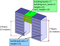
| min_height=* | Approximate height below the building structure. min_height can be used to model overhanging structures, e.g. buildings on inclined ground with one side being supported by pillars. min_height can be applied to building parts that are not connected to the ground, e.g. bridges connecting buildings. When modelling buildings by vertically stacking building parts, then min_height should be used in order to avoid volume intersections.
Note that when min_height is used, height is still defined as the distance from the ground to the top of the structure. As an example, a bridge 10 meters above ground and 3 meters high shall be tagged as min_height=10, height=13. |
|
|
| building:min_height=* | same as min_height=* | ||
| building:levels=* | Number of floors above ground up to the cullis or visible edge (without levels in the roof). The metric height value can be derived from levels by multiplying with an average height value per level. By default this is 3,0 meters, but it can be adjusted based on the type of the building or other properties (age, country, usage etc.). | ||
| levels=* | same as building:levels=* | ||
| building:min_level=* | Lower levels skipped in a building or building part, analogous to min_height. min_height can be computed by multiplying with average height per level (default: 3,0 meters). | ||
| min_level=* | same as building:min_level=* | ||
| colour=* | Colour used for rendering all building elements. Colour values can be either provided as well-known strings or in hexadecimal notation, e.g. #ffffff for white. The set of colour values that shall be supported is listed on this page. | ||
| building:material=* | Information on the material that is visible on most parts of the building. Renderers can use this information in order to improve the visual quality by applying generic textures, specific shaders or typical colours. The following values shall be supported:
brick, concrete, eternit, glass, metal, mirror, plaster, sandstone, slate, stone, timber_framing, wood |
 slate slate
|
|
| roof:colour=* | Colour used for rendering the roof part. Colour values can be either provided as well-known strings or in hexadecimal notation, e.g. #ffffff for white. The set of colour values that shall be supported is listed on this page. roof:colour overrides colour. | ||
| building:roof:colour=* | same as roof:colour=* | ||
| roof:material=* | Information on the material of roof constructions. Renderers can use this information in order to improve the visual quality by applying generic textures, specific shaders or typical colours. The following values shall be supported: roof_tiles, copper, concrete, glass, slate, stone, tar_paper, grass, gravel, wood, metal, eternit, thatch, plants. Detailed description on page roof:material=*. |  wood wood
|
|
| building:colour=* | Colour used for rendering façade elements. Colour values can be either provided as well-known strings or in hexadecimal notation, e.g. #ffffff for white. The set of colour values that shall be supported is listed on this page. building:colour overrides colour. | ||
| building:facade:colour=* | Colour used for rendering façade elements. Colour values can be either provided as well-known strings or in hexadecimal notation, e.g. #ffffff for white. The set of colour values that shall be supported is listed on this page. building:facade:colour overrides both building:colour and colour, but is not interpreted by some of the renderers. | ||
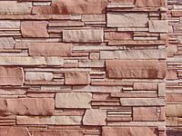
| building:facade:material=* | Information on the material that is visible on facades. Renderers can use this information in order to improve the visual quality by applying generic textures, specific shaders or typical colours. The following values shall be supported:
brick, concrete, eternit, glass, metal, mirror, plaster, sandstone, slate, stone, timber_framing, wood |
 sandstone sandstone
|
LOD 2 - Detailed Building Representations
More detailed representations can be realized by adding roof shapes and describing buildings using multiple parts. The tag building:part=* is used to denote smaller elements with specific roof shapes or materials. The size of building parts must be big enough to represent architecturally important features. This may include building sections, towers, wings, larger roof constructions, spires, columns, pillars, steps, balustrades as a whole, and porches. Building parts shall not be used to model façade details such as windows, ledges, small pergolas, capitals of columns, small balconies, loggias, flags, decorative elements etc. As a general rule, the number of referenced nodes should not exceed TBD per building. Renderers can skip elements if the model is made up of too many elements. Larger structures such as stadiums or airport terminals may require more nodes in order to be modeled adequately. In this case, the tag landmark=* can be used to allow for more elements.
Building parts
In LOD 2 it is possible to replace the building outline with a set of building:parts, which are tagged with building:part=yes or building:part=type of building:part. building:parts can be described using the same attributes as used for buildings. If buildings are described by multiple parts, then the building outline tagged as building=* is no longer considered for volume rendering. Therefore, please fill the whole area of the building with building:part=yes elements, if possible sharing the same nodes.
In general, building:parts with overlapping areas and intersecting 3D volumes are allowed, which is a convenient way to model supporting structures such as pillars etc. However, be aware of the following cases:
- If a building is split into horizontal slices (floors with different ground plans stacked on top of each other), please add min_height=* or building:min_level=* in order to avoid larger vertical intersections, which may slow down 3D rendering.
- Please avoid building:parts sharing façade or roof faces, but with different colour or material. Shared faces result from reusing way segments and intersecting vertical extents. 3D renderers will produce visual artifacts (“z-fighting”) in this case.
Building relation
In order to find out, which building:parts belong together and constitute a single building, and for detecting building=* ways that must be ignored for 3D rendering, a building relation shall be used.
The following core elements of building relation shall be supported:
| Key | Value | Discussion |
|---|---|---|
| type | building | A relation that combines all node, ways, and other relations that belong to a single building. |
Members
LOD 2 attributes
In addition to the height, colour and material attributes described above, the following attributes can be used in LOD 2. These attributes can be used on building=* and building:part=yes elements.
| Key | Comment | Image | TagInfo |
|---|---|---|---|
| roof:shape=* | Characterization of the roof shape using a catalogue of well-known roof types. | 
|
|
| building:roof:shape=* | Same as roof:shape | ||
| roof:orientation=along/across | For roofs with a ridge the ridge is usually assumed to be parallel to the longest side of the building (roof:orientation=along). But it can be tagged explicitly with this tag. Allowed values: along or across. | 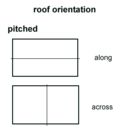
|
|
| roof:height=* | Roof height in meters. Vertical distance from cullis to roof top. roof:height is not applicable for flat roofs. | ||
| roof:angle=* | Alternatively to roof:height, roof height can be indicated implicitly by providing the inclination of the sides (in degrees). | ||
| roof:levels=* | Number of floors within the roof, which are not already counted in building:levels. roof:levels is not applicable for flat roofs. | ||
| roof:direction=* | Direction from back side of roof to front, i.e. the direction towards which the main face of the roof is looking. Mostly used in combination with skillion and other asymmetrical roof shapes. Directions values are either given as N, E, S, W, NE, SE, SW, NW, or as number in degrees (in clockwise order). |
Roof shapes
The following roof shapes are supported by this specification. Additional roof types and geometric parameters for more control over the 3D reconstruction process are supported only by specific renderers. Each roof type is specified by a set of rules, which shall be implemented by 3D renderers. The base height of the roof is usually defined by height=* minus roof:height=*. If these tags are not available, then building:levels=*, roof:levels=* or roof:angle=* must be used to compute the base height. If none of the tags are available, then a default roof height of 3.0 m shall be used. Many roof types assume that the area used as base for the roof structure has a rectangular area. This rectangle usually has two short sides and two long sides, which are used to determine the position of gables and the alignment of ridges (along/across). Often the building is not exactly rectangular or shaped differently. In this case, the Oriented Bounding Box (OBBox) must be first computed from the building ground plan.
| Type | Rules for 3D reconstruction | Diagram | Image | TagInfo |
|---|---|---|---|---|
| flat | Roof top is a flat polygon at the level specified by height=* or building:levels=* | 
|
||
| skillion | Roof with a single sloping face. The roof is constructed as a polygon like for a flat roof, but the involved vertices have different heights | 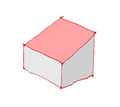
|
||
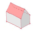
| gabled | Dual pitched roof with one or more gables. | 
|
|
|
| half-hipped | Dual pitched roof with one or more gables being partly clipped at the top | 
|

|
|
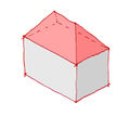
| hipped | Roof where all sides slope downwards to the walls | 
|
|
|
| pyramidal | Roof with faces converging at a single tip point and straight edges. The base of the roof matches the upper wall edges to form a closed volume. The pyramidal roof surface is not necesarily quadratic. | 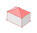
|
||
| gambrel | Two-sided roof with two slopes on each side, the lower slope being steeper than the upper. | 
|
||
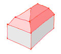
| mansard | Roof having two slopes on every side, the lower slope being steeper than the upper. | 
|
|
|
| dome | Roof with faces converging at a single point forming a kind of hemisphere, possibly distorted. The base of the roof matches the upper edges of the walls to form a closed volume. The roof surface at the base is almost vertical, the tip is almonst horizontal. | 
|
||
| onion | A dome whose shape resembles an onion | 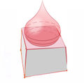
|
||
| round | Curved roof that is curved like a cut-away barrel | 
|
Oriented Bounding Box (OBBox)
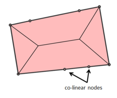
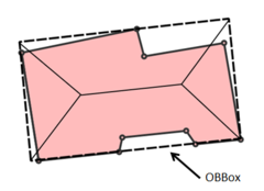
Gabled, half-hipped, hipped, gambrel, mansard, and round roof types assume that the base has a rectangular shape. If the area of building=* and building:part=yes is not rectangular, then the OBBox shall be computed and used for the roof construction. In case of mulipolygon relations, only the outer boundary is considered. The following rules apply:
- If the area has only 4 corner nodes, then the shape shall not be modified. Longer and shorter sides are detected and used for the roof construction, even if the opposite sides are not exactly parallel.
- If the area has only 4 corners, but more than 4 nodes with some being co-linear, then the rectangle formed by the 4 corner nodes is used for the roof construction. The maximum tolerance distance for detecting co-linear nodes is 0.10 m.
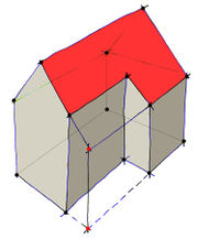
- If the area has more than 4 corners (convex or concave), e.g. forming an L-shaped polygon, then the OBBox is computed and used for the roof construction. In this case, the roof will not exactly fit on the walls and some parts will be overhanging. It is possible to clip away the overhanging parts by extending the walls upwards to meet the roof surface. However, this is an optional operation.
| Image | 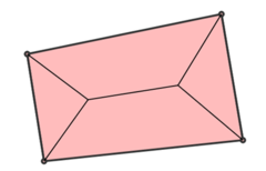
|
|
|
|
|---|---|---|---|---|
| Case | polygon with 4 corner nodes | polygon with co-linear nodes | irregular polygon | optional clip operation |
Tool support
The following 3D tools support this specification
- OSM2World (partial support, currently implementing the remaining features for the 0.2.0 release) - see the slippymap
- Kendzi3d (supported)
- OSM-3D (partial support, see OSM-3D#Buildings)
- Nutiteq Android 3D mapping SDK [1] (most roof shapes supported)
- WikiMiniAtlas (partial support, only pyramidal roofs)
- OSMBuildings (partial support)
- F4 Map - see the [2]
- OpenScienceMap - [3] Interprets only height/min_height tags client-side. The S3DB Layer uses vtm meshes generated on the server (using plpgsql with PostGIS and SFCGAL).
- OSG-Maps (partial support)
