Proposal:Pumping proposal
| The Feature Page for this approved proposal is located at Tag:man_made=pump |
| Pumping proposal | |
|---|---|
| Proposal status: | Approved (active) |
| Proposed by: | fanfouer |
| Tagging: | man_made=pump |
| Applies to: | |
| Definition: | Propose to improve many kind of pumps mapping and description with man_made=pump |
| Statistics: |
|
| Draft started: | 2020-02-29 |
| RFC start: | 2020-03-19 |
| Vote start: | 2020-12-21 |
| Vote end: | 2021-01-04 |
Proposal
It is proposed to make three new tags approved to describe pumps used for any activity regarding liquids only :
- New feature tag for nodes only: man_made=pump "A device in charge of raising level or move liquids only". Only applicable for liquid substance=*s.
- mechanical_driver=* "The motion source powering a pump"
- mechanical_coupling=* "Mechanical power adaption and transformation equipment linking a driver to a pump device"
Introduce a new tag pump_mechanism=*: "Specifies the pump device mechanism that directly moves gases or liquids". Applicable with any gas or liquid substance=*s.
List of 15 new approved values out of Wikipedia classification related to pump mechanisms is given below.
It is proposed to deprecate the use of undocumented pump:type=* to state pump mechanisms in favour of new pump_mechanism=*.
The proposed tagging scheme will also deprecate man_made=pumping_rig and propose to replace it with man_made=petroleum_well or man_made=water_well and pump_mechanism=* (mainly with rotating driver and pump-jack coupling).
Dedicated devices used to drive pumps will be described with mechanical_driver=* and optionally completed with mechanical_coupling=*.
The tag handle=* is already approved for use with pipeline valves, and it will be approved for use with manual pumps or emergency usage with manual action when power isn't available.
By the way, this proposal focuses on pumps and then liquids but proposed pump_mechanism=* values would be used the same way on gas compressors which will require a different man_made=* entry.
Pumps differ from several other devices and as such the two following machines will not be included in this proposal:
- Fans: A machine intended to create a flow of gas (often air)
- Compressors: An assembly including a pump intended to compress gases
Rationale
Two primary motives and outcomes of this proposal:
- Refining tagging model as proposed will improve knowledge and systematic characterization of man made pneumatic and hydraulic systems like water wells in developing countries or more complex industrial facilities in developed areas.
- Proposed tagging will allow the mapping of pumps beyond water wells only.
How and why:
Pumps are mechanical devices to move liquids and are a common component of industrial systems and water supplies. They can have many different shapes and functions. They are found in many settings, from households to heavy industries.
As they cover many activities, several pumping mechanisms exist and are adapted to field or fluids constraints and the available energy sources. Consumers may have interest to know their purpose, system characteristics, pipes connections and the source(s) of the incoming fluid.
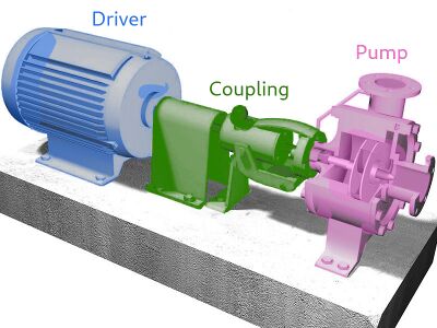
Three main components comprise a typical pump assembly: 1. Driver 2. Coupling and 3. Pump, but to date OSM tagging has not allowed for the inclusion of this additional information.
Note that pumps are usually powered by a driver through a coupling mechanism. To clarify:
- The driver in any assembly is in charge of the conversion from the source energy to a mechanical force.
- A coupling is in charge of transmitting the power by connecting the driver and the pump mechanism.
Driver technology is not the same as pump mechanism: for instance the same reciprocating pump can be independently driven by either hand or by an electric motor.
Coupling is not the same as the driver's motion source: for instance the same nodding donkey coupling can independently adapt motion from electric motor, combustion engine or even manual power.
Wikipedia and other encyclopedias provide a complete classification of pumps with several considerations: principle, engineering, history and use cases (not to mention practical implementations). OSM will rely on Wikipedia's classification as to not create another classification but ground-proof tagging method for mappers to classify pumps with practical and available criteria.
Proposed pump_mechanism=* values will allow mappers to determine which kind of pump they see on ground (see examples). Quantifiable figures and capacities are obtained from public documentation or read in place (via nameplates or pump tags). No import from any database is planned following this proposal as contributions are expected from on-site surveys.
Proposed tagging will cover:
- Pump mechanism
- Driver technology & rating
- Pump and driver coupling
- Maximum volume the pump can move (generally in m3/s or m3/h)
This proposal focuses on tags to use if, and only if, data is available. It does not assume all data can be publicly known but provide a consistent model to add it to the map if possible, without any pipeline operator help. If you can't reach a particular device, then don't map it.
How to map
First of all, don't go inside private or restricted perimeters if you're not invited to do so please, some pumps may not be safely accessible and you may expose yourself to multiple hazards.
Public information or aerial imagery will help to see outdoor pipeline facilities safely.
On every pump device (not the surrounding perimeter nor building) found, place a ![]() and add the tag man_made=pump (if no other man_made=* value prevents it as explained below).
and add the tag man_made=pump (if no other man_made=* value prevents it as explained below).
Use location=* to give information about its position and pump_mechanism=* to let us know about its mechanism.
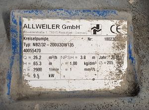
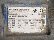
High detailed information may be found on pumps themselves. A complete datasheet may be posted next to the pump which shows the device capabilities and mechanism (see beside).
Nevertheless, you may not be permitted to take a photo of those plates and as a reminder : don't go inside restricted perimeters to get the one you couldn't unless invited.
man_made=pump is only proposed for individual pump devices.
Pumping stations
This proposal won't change how man_made=pumping_station is used on buildings.
Pumps used in industry and located inside technical buildings called pumping stations are covered by this proposal.
Mappers may find publicly available documentation or be able to see from public space how pumps are installed inside and apply guidelines upside.
Every pump should get its own OSM node inside the building, approaching their actual position, with appropriate tagging described below.
Wells
Proposed pump_mechanism=* values can be used in combination with established man_made=water_well, man_made=petroleum_well or any other drilling.
The point of this proposal is to complete existing features with more elaborated information about pumping capacities. Then a dedicated man_made=pump shouldn't be created beside if the pump is directly installed in the well or on the wellhead.
Wind pumps
Proposed pump_mechanism=* values can be used in combination with established man_made=windpump which refer to an assemble of blades taking kinetic energy from wind and driving a pump on the ground.
As to maintain a difference with traditional man_made=windmill, a dedicated man_made=pump shouldn't be created beside if the pump is directly part of the wind pump.
Tagging
| Key | Value | Comment | Recommendation |
|---|---|---|---|
| man_made | pump | Pumps are usually mapped as |
mandatory |
| windpump | A wind pump is a particular windmill driving a pump to extract water from ground. | mandatory | |
| water_well (or any well) | A structural facility to access ground water, created by digging or drilling. Here with the help of a pump | mandatory | |
| pump_mechanism | <pump mechanism> | The mechanical design of the pump | recommended |
| mechanical_driver | <driver technology> | Motion source of the pump | recommended |
| mechanical_coupling | <coupling technology> | Mechanical equipment linking driver and the pump to transmit torque. Defaults to direct | recommended |
| handle | <handle model> | Does a handle is available on the pump to operate manually? See below for possible values | optional |
| location | <location> | The physical location of the pump, such as indoor. See below for possible values. | optional |
| operator | <operator> | Name of the company that operates the pump. | optional |
| manufacturer | <Manufacturing company> | Name of the company that built the pump (and possibly its driver) | optional |
| ref | <reference> | Abbreviation / number of the pump. | optional |
| pressure | <nominal output pressure in bar> | Nominal output pressure the pump is designed to deliver | optional |
| flow_rate | <nominal output flow in m3/s> | Nominal output flow the pump can deliver. | optional |
Althought it is not usually recommended to add properties of incoming pipelines to accessory nodes, it is correct to add substance=* on pump nodes to state which substance is processed by a particular device, especially when pumps don't operates mixtures or change the state of the substance.
Pump mechanisms
Mechanisms classification is taken directly out from Wikipedia classification that anyone can read to understand how each work.
These pumps are also compatible with compressors as show in this second article.
| Key | Classification | Value | Comment |
|---|---|---|---|
| pump_mechanism | Positive displacement | gear | Gear pump involves two or more wheels touching each other as to intake, effectively displace and then output processed fluid. It covers Lobe pump and Roots-type supercharger. |
| screw | Screw pump involve a screw - with a continuous cavity - to move the fluid along its axis. It covers Archimedes' screw if and only if carries a fluid. It is not a progressive cavity pump. | ||
| progressive_cavity | Progressive cavity pump is different from a screw pump as moving part is composed of discrete cavities moving around an axis. Cavities get the fluid during intake and displace it along the chamber to the output with a positive pressure. | ||
| diaphragm | Diaphragm pump is often a double chamber pump than sequentially fill and empty due to a diaphragm action driven by electric or pneumatic cylinders. | ||
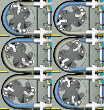
| peristaltic | Peristaltic pump involves a flexible fluid chamber pushed by external roller which both intakes and outputs fluid outside the pump. It is most used in biomedical appliances which requires to let fluid untouched from external component. | ||
| rope | Rope pump is built from a piece of rope with disks or knots attached and matching the pump chamber diameter immersed in processed fluid. Moving the rope displaces the fluid out of pump chamber with a positive pressure. | ||
| rotary_vane | Rotary vane pump is composed of a rotary wheel with vanes pushing the fluid out of pump chamber. Vanes dimension can change as to match orregular pump chamber diameter or shape. This includes radial piston or flexible impeller. Such impellers don't transmit kinetic energy to processed fluid until you find a centrifugal pump (see below) | ||
| piston | Piston pump involves a reciprocating moving part that sequentially sucks fluid into the pump chamber and pushes it out. It covers Plunger pump and Beam engine. It is different than a Diaphragm pump as the diaphragm doesn't plunge into the fluid and doesn't move like a piston. | ||
| Velocity | centrifugal | Centrifugal pump involves a high speed rotating impeller transmitting kinetic energy to processed fluid. Radial pumps gets fluid direction changed often by 90° angle from intake while inline pump can exists as well. This speed may be converted latter into fluid pressure while it exits the pump in the discharge pipe. | |
| axial_flow | Axial flow pumps use a high speed rotating impeller directed in the axis of the processed fluid flow. Direction of the fluid remains unchanged and the speed may be converted latter into fluid pressure depending of the discharge pipe design. | ||
| eductor_jet | Eductor jet pumps may be used in water wells to push out water with the help of pressurised air injection. Most commonly known as injector this value only regards usage as pump. | ||
| Gravity | ram | (Hydraulic) ram uses high flowrate hydropower to deliver fluid at a higher pressure but lower flowrate than intake. Hydropower energy is converted in mechanical form with the help of gravity. | |
| siphon | Siphons may be used as pumps to deliver a small amount of fluid at a higher level than reservoir with the help of most part of the fluid as gravity driver in a closed cycle. It is quite special and not so common actually. | ||
| Impulse | pulser | Pulser pump requires a constant flow of water running into a closed chamber, mainly coming from upper reservoir. Intake is placed just at the surface of the reservoir and sucks air as it goes down to the chamber. Air gets trapped in the chamber and pushes a part of the water out at a higher level than input reservoir. | |
| airlift | Airlift pump takes advantage of floating air to raise level of processed fluid. Air is inserted in the outlet pipe and pushes fluid higher toward the output. |
Drivers
Drivers are defined as mechanical energy converters and the main source of power for pump mechanisms. They can work from many sources of energy: electricity, steam, wind, electromagnetic forces, etc.
Drivers are only motion sources and require a coupling to transmit the power to the pump mechanism.
mechanical_driver=* new key shouldn't be confused with actuator=* which describe devices intended to mechanically control some processes and don't act as primary motion sources.
| Key | Value | Comment |
|---|---|---|
| mechanical_driver | manual | Hands as the main way to drive the pump |
| electric_motor | An electric motor or regular engine converts electricity or combustion to mechanical energy and drives pump with rotary motion | |
| combustion_engine | A combustion engine is a regular combustion motor fed by oil or gasoline to produce a rotary movement | |
| reciprocating_solenoid | A solenoid can be used to produce reciprocating motion used to drive some kind of pumps. This video shows it in action | |
| cylinder | Pneumatic or hydraulic cylinders are used as drivers for pumps requiring reciprocating motion. See this double diaphragm pump. | |
| turbine | A turbine runner provides mechanical power out of a liquid or gaseous flow at a positive pressure. So-propelled pumps are called turbo pumps |
In case of manual driver, existing handle=* will help to define how users are supposed to move the pump. It's proposed to add additional values suitable here
| Key | Value | Comment |
|---|---|---|
| handle | crank | Handle converting reciprocating movement into rotation or vice-versa |
Existing handle=lever is suitable to some pumps as Wikipedia deals with it for hand pumps. Lever pumps are actually piston/diaphragm/... pumps with lever driver. It sounds to be a 3rd class lever.
Lever handle sounds to have different forms and this is what we get when looking for them 3 :
- Door handle : The most common types of door handle are the lever handle and the doorknob.
- Ball valve : Lever handle (on the first chart)
- Hand pump (kind of lever is a hand pump) : Piston rod + force rod = lever.
Couplings
As motion often needs to be adapted, drivers can be more complex than a simple motion source and could include a mechanical adapter (gear reducer, nodding donkey...). Torque can be adapted in different ways from a single given electric motor for instance.
Couplings are passive equipment and not a motion source. They are particularly useful for pumps as they put impellers or pistons in motion and efficiently move the processed fluid.
| Key | Value | Comment |
|---|---|---|
| mechanical_coupling | direct | The power out of driver is directly transmitted to pump mechanism without any adaptation nor transformation |
| reducer | A reducer adapts rotating motion to an appropriate rotating torque for the pump mechanism with help of gears to provide a static ratio | |
| gearbox | A gearbox adapts a rotating motion to an appropriate torque force with the ability to change ratio according to mechanical needs at a given time | |
| nodding_donkey | A nodding donkey converts the rotary movement of a motor/engine to a reciprocating motion used to drive some kind of pumps. | |
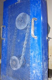
| belt | A belt allows to transmit motion between two parallel axes with possibly different diameters to adapt torque. |
List can be completed with any additional value to cover situations we didn't include here.
Edition management
Keys to be replaced or completed
There is no automated edit planned once this proposal reviewed. All replacements will be done manually with caution on every feature.
| Obsolete tag | Usage volumetry | Used for ? | New tag(s) to use |
|---|---|---|---|
| man_made=pumping_rig | 2 495 2020-03-19 | A piston pump used on oil/gas wells, powered by pump-jack driver | man_made=petroleum_well + substance=* + pump_mechanism=piston + mechanical_driver=combustion_engine + mechanical_coupling=nodding_donkey |
| A piston pump used on water wells (see this video), powered by pump-jack driver | man_made=water_well + pump_mechanism=piston + mechanical_driver=combustion_engine + mechanical_coupling=nodding_donkey | ||
| pump:type=beam_pump | 1 580 2020-03-18 | A piston pump used on oil/gas wells, powered by pump-jack driver | man_made=petroleum_well + substance=* + pump_mechanism=piston + mechanical_driver=combustion_engine + mechanical_coupling=nodding_donkey |
| A piston pump used on water wells (see this video), powered by pump-jack driver | man_made=water_well + pump_mechanism=piston + mechanical_driver=combustion_engine + mechanical_coupling=nodding_donkey |
Affected pages
- Create man_made=pump page
- Create mechanical_driver=* page
- Create mechanical_driver=manual
- Create mechanical_driver=electric_motor
- Create mechanical_driver=combustion_engine
- Create mechanical_driver=reciprocating_solenoid
- Create mechanical_driver=cylinder
- Create mechanical_coupling=*
- Create pump_mechanism=* page and add proposed values
- Edit man_made=water_well page and add optional tag to use in combination
- Edit man_made=windpump page and add references to appropriates pump_mechanism=* values
- Edit flow_rate=* page to mention man_made=pump
- Deprecate man_made=pumping_rig page
- Deprecate pump:type=beam_pump page
Examples
Local supply
| Photo | Location | Tagging | Comments |
|---|---|---|---|
 |
Germany |
man_made=pump
|
A piston pump used to get water by manually raising and lowering the lever. The piston is located underground and move water towards the faucet and then outside of the well |
 |
USA | A wind pump in a farm in USA involving a piston pump (apparently, on the ground) driven by a windmill and possibly actuated by hand with the help of a lever as well in case of lacking wind. | |
 |
Mali |
man_made=water_well
|
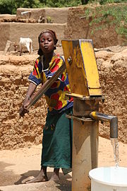
A manual piston pump installed on a water well head in Mali. Water well, piston pump and manual driver (with handle) are 3 independent objects described on the same OSM node here |
 |
Tanzania |
man_made=water_well
|
A manual rope pump installed on a water well head in Tanzania. Water well, rope pump and manual driver (with crank handle) are 3 independent objects described on the same OSM node here |
 |
Africa |
man_made=water_well
|
A standard electric submersible pump with electric motor to power a multi-stage centrifugal impeller. Intake is located on the pump body side and centrifuguation makes the water go out on top. |
 |
England | A hydraulic ram converts high flow kinetic energy into a pressure for a smaller flow, allowing it to be actually pumped. It requires no driver and external power supply so mechanical_driver=* isn't applicable here. This ram is beside an actual well head under the concrete plate behind it. |
Industrial
| Photo | Location | Tagging | Comments |
|---|---|---|---|
 |
France |
man_made=pump
|
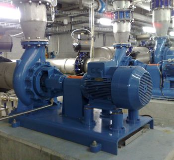
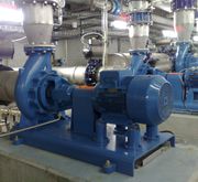
A common radial centrifugal_pump driven by an electric motor in a drinkable water production facility |
 |
The Netherlands |
man_made=pump
|
A common radial centrifugal_pump driven by an electric motor probably used for irrigation or water reservoir feeding |
 |
- |
man_made=pump
|
An inline centrifugal_pump driven by an electric motor. Centrifugal pumps can sometimes find inline, with less axial efforts than radial ones. |
 |
Austria |
man_made=pump
|
A common progressive_cavity_pump driven by an electric motor used for oil pumping in heavy machinery. See below for running principle |
 |
Wyoming, USA |
man_made=petroleum_well
|
A common pumpjack collecting oil from underground well. We know it is driven by an electric motor instead of an engine by looking at electric power supply on the right. |
 |
International sea |
man_made=pump
|
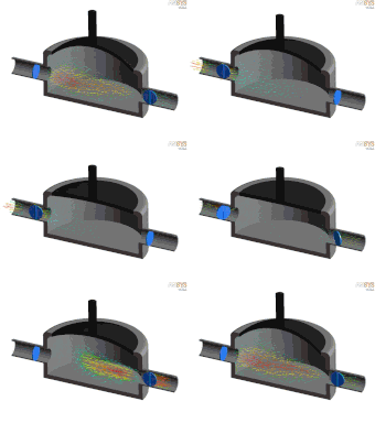
A common diaphragm pump driven by a pneumatic cylinder, installed here on a boat deck (so please don't map it in place). This example shows the diaphragm shape that can't be confused with any other mechanism. See below for running principle |
 |
France |
man_made=pump
|
This example focus on coupling an electric motor to centrifugal pump with a belt. Both pump and motor are behind the blue casing |
 |
- |
man_made=pump
|
Pumps figure plates can help to define OSM tags values. Here is how this example is evaluated: |
 |
USA |
man_made=pump
|
A peristaltic pump involved in a chemical process with potentially dangerous fluids. The box between the electric motor and the pump is a reducer to slow the rotation speed and increase the torque as to move the fluid in the pipe |
 |
Germany | A rotary vane pump mechanism only where driver and coupling remain undetermined. See below for running principle | |
 |
Nederlands |
man_made=archimedes_screw
|
An archimede's screw moving a fluid to a higher level. |
Hydropower
| Photo | Location | Tagging | Comments |
|---|---|---|---|
 |
Switzerland |
man_made=pump
|
Hydropower generation sometimes involves pump for large scale water storage. Some power plants have pumps separated from turbines like in Veytaux, Switzerland where a 600 tons multi-stage centrifugal pump is located below a Pelton turbine, linked by a direct coupling (see this chart). The pump is driven by the generator used as an electric motor with electricity coming from transmission grid. When the pump s running, the Pelton turbine runs empty without water. |
See also
- IEEE Engineering 360 portal about pumps
- LEWA pumps navigator to help designing a pump solution based on factual criteria. (Disclaim: this link is not here for commercial reasons and this proposal isn't supported by the company by any means)
- Differences between pumps and fan topic on Physics Forum
- Differences between pumps and compressors
External Discussions
- February 2020
- [Tagging] man_made=petroleum_well vs man_made=pumping_rig
- [Tagging] Mapping pumps
- March 2020
- [Tagging] Mapping pumps
- [Tagging] Feature Proposal - RFC - Pumps (wells and many other things)
- [Tagging] Pumps (wells and many other things)
- November 2020
- [Tagging] Feature Proposal - Voting - Pumping proposal
- [OSM-talk-fr] Proposition - Vote - Les pompes
- [Hot/Hdm] info about attempted deprecation of pump tag
- [OSM World Discord #tagging] Discussion about tag keys and conflict with old tag (First part is slightly off-topic, scroll down a bit)
Voting
First voting round
First voting results has been archived here.
Second voting round
Voting on this proposal has been closed.
It was approved with 20 votes for and 1 vote against.
 I approve this proposal. Nice job! --Leebob (talk) 16:02, 4 January 2021 (UTC)
 I approve this proposal. --Adiatmad (talk) 23:07, 3 January 2021 (UTC)
 I approve this proposal. --Komadinovic Vanja (talk) 14:33, 22 December 2020 (UTC)
 I approve this proposal. Great work, very comprehensive! --ZeLonewolf (talk) 00:59, 21 December 2020 (UTC)
 I approve this proposal. --Brian de Ford (talk) 01:03, 21 December 2020 (UTC)
 I approve this proposal. Question: Are you adopting the bar unit definition in pressure=*? I understand it's the common unit, but looks a bit odd alongisde m^3/s flow_rate=*. ---- Kovposch (talk) 09:46, 21 December 2020 (UTC)
- This proposal doesn't modify pressure=* and its unit is bar. No problem to use other explicit units if required anyway. Fanfouer (talk) 23:14, 4 January 2021 (UTC)
 I have comments but abstain from voting on this proposal. Agree with Kovposch. Use proper SI units if possible. kPa or MPa would be appropriate for pumps. Noted that Bar is used, but it is generally deprecated. Exception - In USA pounds per square inch (psi) would apply. - Craig.za (talk) 12:41, 26 December 2020 (UTC)
 I approve this proposal. Comprehensive proposal, supported! --B-unicycling (talk) 10:42, 21 December 2020 (UTC)
- This proposal doesn't modify pressure=* and its unit is bar. No problem to use other explicit units if required anyway. Fanfouer (talk) 23:14, 4 January 2021 (UTC)
 I approve this proposal. Lenny (talk) 18:32, 21 December 2020 (UTC)
 I approve this proposal. --Dr Centerline (talk) 00:22, 22 December 2020 (UTC)
 I oppose this proposal. It is weird that pump=* was not mentioned at all (it probably should be as simple and valid tagging that can be made more detailed by this new tags) Mateusz Konieczny (talk) 13:20, 26 December 2020 (UTC)
- pump=* exists and will be preserved in water wells documentation. It wasn't mentioned in this proposal as to make it clear nothing changes about its status following this vote and comment received after first vote Fanfouer (talk) 23:14, 4 January 2021 (UTC)
 I approve this proposal. --Renecha (talk) 11:22, 29 December 2020 (UTC)
 I approve this proposal. --Manu 4BB9A (talk) 18:09, 3 January 2021 (UTC)
 I approve this proposal. --TheBlackMan (talk) 13:44, 3 January 2021 (UTC)
 I approve this proposal. See first voting round for my comments. Thank you for the proposal ! --Gileri (talk) 13:52, 3 January 2021 (UTC)
 I approve this proposal. --DenisHelfer (talk) 17:34, 3 January 2021 (UTC)
 I approve this proposal. Requests for changes have been made. It's great! --Gendy54 (talk) 17:40, 3 January 2021 (UTC)
